Zhang K., Li D. Electromagnetic Theory for Microwaves and Optoelectronics
Подождите немного. Документ загружается.

5.4 Waveguides and Cavities in Circular Cylindrical Coordinates 271
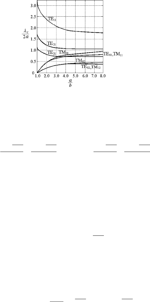
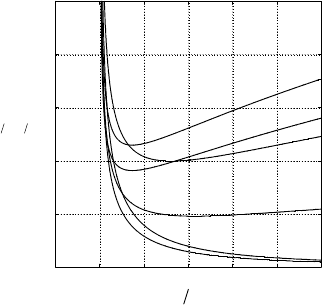
Figure 5.23: Cutoff wavelengths of the TM and TE modes in a coaxial line.
The cutoff wavelengths of the TM
nm
and TE
nm
modes of the coaxial line
are given as follows:
λ
c
TM
nm
=
2π
√
µ
r
²
r
T
TM
nm
=
2πb
√
µ
r
²
r
x
nm
, λ
c
TE
nm
=
2π
√
µ
r
²
r
T
TE
nm
=
2πb
√
µ
r
²
r
y
nm
, (5.186)
which are shown in Fig. 5.23.
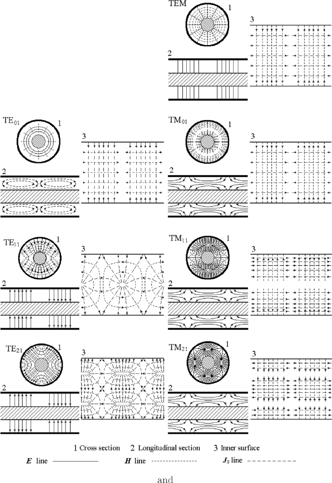
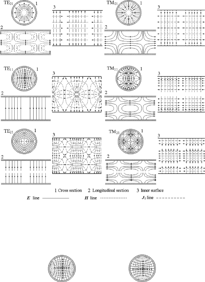
The field maps of some lower-order modes in coaxial line are shown in
Fig. 5.24.
The lowest-order TM mode is TM
01
. The field distribution of the TM
01
mode in a coaxial line is similar to that of the TM
1
mode in a parallel-plate
line, shown in Figure 5.14, especially when the space between the inner and
outer conductors is small, a − b ¿ a. So the approximate cutoff wavelength
for the TM
01
mode in coaxial line is given by
λ
c
TM
01
≈ 2(a − b)
√
µ
r
²
r
. (5.187)
The lowest-order TE mode is TE
11
. The field distribution of the TE
11
mode in a coaxial line is similar to that of two TE
10
modes in the rectangular
waveguide, shown in Fig. 5.5, especially when the space between the inner and
outer conductors is small, a − b ¿ a. So the approximate cutoff wavelength
for the TE
11
mode in a coaxial line is given by
λ
c
TE
11
≈ 2
µ
π
a + b
2
√
µ
r
²
r
≈ π(a + b)
√
µ
r
²
r
. (5.188)
The lowest non-TEM mode in a coaxial line is the TE
11
mode, because
λ
c
TE
11
> λ
c
TM
01
.
272 5. Metallic Waveguides and Resonant Cavities
Figure 5.24: Field maps of TEM and some TE, TM modes in a coaxial line.
5.4 Waveguides and Cavities in Circular Cylindrical Coordinates 273
(2) TEM Mode in Coaxial Line
The TEM mode is the dominant mode in a coaxial line in which T = 0, β = k,
E
z
= 0, H
z
= 0. The transverse vector equations of the electromagnetic fields
become two-dimensional vector Laplace equations,
∇
2
T
E
T
= 0, ∇
2
T
H
T
= 0, (5.189)
and the equations for U and V are two-dimensional scalar Laplace’s equa-
tions,
∇
2
T
U = 0, ∇
2
T
V = 0. (5.190)
In the two-dimensional polar coordinates, the angular homogeneous solu-
tions of Laplace’s equation take the following form:
U(ρ) = A + B ln ρ, U(ρ, z) = (A + B ln ρ)e
−jβz
. (5.191)
Substituting this into the field-component expressions yields
E
ρ
= −jk
∂U
∂ρ
=
E
0
ρ
e
−jβz
, H
φ
= −jω²
∂U
∂ρ
=
E
0
ηρ
e
−jβz
, (5.192)
E
φ
= 0, E
z
= 0, H
ρ
= 0, H
z
= 0,
where E
0
= −jkB. These are the field components of the TEM mode in a
coaxial line with short-circuit boundaries.
The characteristic impedance of the TEM mode in coaxial line is obtained
by (3.70), as follows,
Z
c
=
R
a
b
(E
0
/ρ)d ρ
R
2π
0
(E
0
/ηρ)ρd φ
=
1
2π
ln
a
b
η. (5.193)
Propagation of a single TEM mode can be realized in a coaxial line only
under the following condition:
λ > λ
c
TE
11
, λ > π(a + b)
√
µ
r
²
r
. (5.194)
A section of coaxial line closed by short-circuit or open-circuit terminals
at the two ends becomes a coaxial cavity. The coaxial cavity shorted at both
ends is a λ/2 cavity and the coaxial cavity with a short-circuit terminal at
one end and an open-circuit terminal at the other end is a λ/4 coaxial cavity.
A real open end to a coaxial line is not an open-circuit terminal because
of radiation. An open-circuit terminal can be realized approximately by
means of a section of circular waveguide with the same diameter as the outer
conductor of the coaxial line and with enough length, which forms a section
of cutoff waveguide and the input impedance is closed to infinity.
Using the angular homogeneous solution of function V , we can have the
dual TEM fields for the coaxial line with open-circuit boundaries.
274 5. Metallic Waveguides and Resonant Cavities
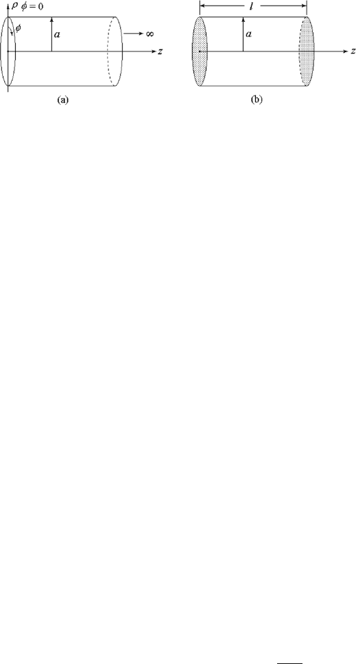
Figure 5.25: (a) Circular waveguide and (b) circular cylindrical cavity.
5.4.4 Circular Waveguides and Circular Cylindrical
Cavities
Taking out the inner conductor of a coaxial line, we have the circular waveg-
uide shown in Fig. 5.25(a). The TEM mode cannot exist in the circular
waveguide because it consists of only one conductor, and static fields can
not exist in it. A section of circular waveguide shorted at both ends forms a
circular cylindrical cavity, refer to Fig. 5.25(b).
(1) Circular Waveguides
The field in a circular waveguide must be continuous around the whole circle,
and ν must be an integer, ν = n. The radial functions of the fields are Bessel
functions with integer order and the angular functions of the fields become
cos nφ or sin nφ, which are standing wave fields similar to those in the coaxial
line. The interesting region of the circular waveguide is the region including
the z axis, ρ = 0, and N
n
(0) → ∞, so the coefficients of the Neumann
functions in the solution must be zero.
The function U for the TM mode or so called E mode in a circular waveg-
uide with an even function with respect to φ is given by
U(ρ, φ, z) = U
0
J
n
(T ρ) cos(nφ)e
−jβz
. (5.195)
Applying the boundary condition of U on the inner surface of the waveguide
wall, ρ = a, we have the eigenvalue equation for TM mode
U|
ρ=a
= 0, J
n
(T a) = 0, T
TM
nm
=
x
nm
a
, (5.196)
where x
nm
denotes the mth ro ot of the Bessel function of the nth order,
J
n
(x
nm
) = 0, see the top half of Table 5.2 [37, 49, 67].
5.4 Waveguides and Cavities in Circular Cylindrical Coordinates 275
Table 5.2
The roots of J
n
(x) = 0
x
nm
n = 0 n = 1 n = 2 n = 3 n = 4 n = 5
m = 1 2.405 3.832 5.136 6.380 7.588 8.771
m = 2 5.520 7.016 8.417 9.761 11.065 12.339
m = 3
8.654 10.173 11.620 13.015 14.372
m = 4 11.792 13.324 14.796
The roots of J
0
n
(y) = 0
y
nm
n = 0 n = 1 n = 2 n = 3 n = 4 n = 5
m = 1 3.832 1.841 3.054 4.201 5.317 6.416
m = 2 7.016 5.331 6.706 8.015 9.282 10.520
m = 3
10.173 8.536 9.969 11.346 12.682 13.987
m = 4
13.324 11.706 13.170
Substituting (5.195) into the expressions for the field components of the
traveling-wave solution in circular cylindrical coordinates in terms of Borgnis’
potentials, (4.196)–(4.201), we have the field-component expressions of the
TM modes in a circular waveguide:
E
ρ
= −jβ
∂U
∂ρ
= −jβT U
0
J
0
n
(T ρ) cos(nφ)e
−jβz
, (5.197)
E
φ
= −
jβ
ρ
∂U
∂φ
= −j
βn
ρ
U
0
J
n
(T ρ) sin(nφ)e
−jβz
, (5.198)
E
z
= T
2
U = T
2
U
0
J
n
(T ρ) cos(nφ)e
−jβz
, (5.199)
H
ρ
=
jω²
ρ
∂U
∂φ
= −
jω²n
ρ
U
0
J
n
(T ρ) sin(nφ)e
−jβz
, (5.200)
H
φ
= −jω²
∂U
∂ρ
= −jω²T U
0
J
0
n
(T ρ) cos(nφ)e
−jβz
, (5.201)
H
z
= 0. (5.202)
The field maps of some lower-order TM modes in a circular waveguide are
shown in Fig. 5.26 (left).
The function V for the TE mode or H mode in a circular waveguide is
given by
V (ρ, φ, z) = V
0
J
n
(T ρ) cos(nφ)e
−jβz
. (5.203)
Applying the boundary condition of V on the inner surface of the waveguide
wall, ρ = a, we have the eigenvalue equation for TE mode
∂V
∂ρ
¯
¯
¯
¯
ρ=a
= 0, J
0
n
(T a) = 0, T
TE
nm
=
y
nm
a
, (5.204)
where y
nm
denotes the mth root of the derivative of the Bessel function of
the nth order, J
0
n
(y
nm
) = 0, see the lower half of Table 4.2.
276 5. Metallic Waveguides and Resonant Cavities
Figure 5.26: Field maps of some lower-order TM and TE modes in a circular
waveguide.
Figure 5.27: Orthogonal degeneration or polarization degeneration of TE
11
modes in a circular waveguide.
5.4 Waveguides and Cavities in Circular Cylindrical Coordinates 277
Substituting (5.203) into (4.196) to (4.201), we have the field-component
expressions of the TE modes
E
ρ
= −
jωµ
ρ
∂V
∂φ
=
jωµn
ρ
V
0
J
n
(T ρ) sin(nφ)e
−jβz
, (5.205)
E
φ
= jωµ
∂V
∂ρ
= jωµT V
0
J
0
n
(T ρ) cos(nφ)e
−jβz
, (5.206)
E
z
= 0, (5.207)
H
ρ
= −jβ
∂V
∂ρ
= −jβT V
0
J
0
n
(T ρ) cos(nφ)e
−jβz
, (5.208)
H
φ
= −
jβ
ρ
∂V
∂φ
=
jβn
ρ
V
0
J
n
(T ρ) sin(nφ)e
−jβz
, (5.209)
H
z
= T
2
V = T
2
V
0
J
n
(T ρ) cos(nφ)e
−jβz
. (5.210)
The field maps of some lower-order TE modes in a circular waveguide are
shown in Fig. 5.26 (right). Note that, the modes with n 6= 0, i.e., circularly
asymmetric modes, have orthogonal degeneration or polarization degenera-
tion, such degeneration for TE
11
modes is shown in Fig. 5.27.
The cutoff angular frequencies and the cutoff wavelengths of the TM
nm
and TE
nm
modes of the circular waveguide are given as follows:
ω
c
TM
nm
=
x
nm
a
√
µ²
, λ
c
TM
nm
=
2πa
√
µ
r
²
r
x
nm
, (5.211)
ω
c
TE
nm
=
y
nm
a
√
µ²
, λ
c
TE
nm
=
2πa
√
µ
r
²
r
y
nm
. (5.212)
The phase coefficient of TM and TE modes are given by
β
TM
nm
= k
r
1 −
(T
TM
nm
)
2
k
2
= k
r
1 −
(x
nm
/a)
2
k
2
(5.213)
β
TE
nm
= k
r
1 −
(T
TE
nm
)
2
k
2
= k
r
1 −
(y
nm
/a)
2
k
2
. (5.214)
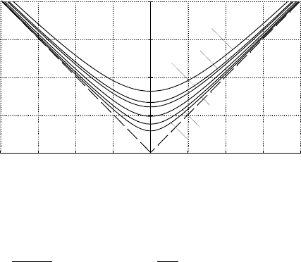
The dispersion curves for the lower-order modes in circular waveguide are
shown in Fig. 5.28.
The attenuation co efficients for the TE and TM modes in a circular waveg-
uide are given by
α
TE
=
R
S
aη
p
1 − T
2
/k
2
µ
T
2
k
2
+
n
2
y
2
nm
− n
2
=
1
a
3/2
σ
1/2
r
y
nm
2η (1 −f
2
c
/f
2
) f
c
/f
µ
f
2
c
f
2
+
n
2
y
2
nm
− n
2
[Np/m], (5.215)
α
TM
=
R
S
aη
p
1 − T
2
/k
2
=
1
a
3/2
σ
1/2
r
y
nm
2η (1 −f
2
c
/f
2
) f
c
/f
[Np/m],
(5.216)
278 5. Metallic Waveguides and Resonant Cavities
0
4S
E
a (rad)
4S
3S
S
2S
2S
3S
S
ka (rad)
S
2S
3S
4S
E
k
TE31
TE01 TM11
TM21
TE11
TM01
TE21
Figure 5.28: Disp ersion curves (k-β diagram) of some TM and TE modes in
a circular waveguide.
where R
S
=
p
ωµ/2σ = 1 /σδ, η =
p
µ/². Plots of the attenuation co effi-
cients for some lower modes in a circular waveguide are shown in Figure 5.29.
The lowest mode in a circular waveguide is the TE
11
or H
11
mode, which
has a cutoff wavelength λ
c
TE
11
= 3.41a. This mode is seen to be the dominant
mode for the circular waveguide. The field map of the TE
11
mode in a circular
waveguide is similar to that of the TE
10
mode in a rectangular waveguide.
The circular waveguide is a rotational symmetric structure, but the field
map of the TE
11
mode is not rotational symmetric. The dominant mode is
actually a pair of degenerate TE
11
modes with sine and cosine variation along
φ, or two polarized modes with the directions of polarization perpendicular
to each other, refer to Fig. 5.27. The fields of the TE
11
mode with an
arbitrary orientation can be seen as the combination of these two degenerate
modes. This kind of degeneration is known as the polarization degeneration
or orthogonal degeneration. All circularly asymmetric or angular nonuniform
modes in circular waveguide have polarization degeneration. Hence there is
no frequency range for real single-mode propagation in the circular waveguide
just the same as in the square waveguide.
The lowest-order circularly symmetric mode in the circular waveguide is
TM
01
or E
01
mode. It is similar to the TEM mode in coaxial line, with
displacement current along the longitudinal axis instead of the current in the
inner conductor of the coaxial line. It is usually used as rotary joint in an
antenna feed and other short distance rotational symmetric system.
The other interesting mode in circular waveguides is the TE
01
or H
01
mode. Since electric field lines are circular, modes of this class, H
0m
modes,
are often described as circular electric modes. It can b e seen from (5.205)–
(5.210) that if n = 0 then H
φ
= 0, and Hρ|
ρ=a
= 0. The only magnetic field
component at the b oundary is H
z
. This means that there is a circumferential
current J
φ
but no longitudinal current J
z
on the inner wall of the waveguide.
This result shows that the energy is carried by fields but not currents or
5.4 Waveguides and Cavities in Circular Cylindrical Coordinates 279
0 1 2 3 4 5 6
0.00
.05
.10
.15
.20
.25
TE01
TM11
TE02
TE11
TE21
TM01
2123
VD
a
c
ff
Figure 5.29: Normalized attenuation coefficients for some modes in a circular
waveguide.
moving charges in electromagnetic transmission systems. It can be seen from
(5.215) and Fig. 5.29 that the attenuation coefficient of the TE
0m
mode is
considerably less than that for other modes and decreases for a guide of fixed
size as the frequency is increased. It is for this reason that considerable
work has been done on theories and techniques for the utilization of the H
01
mode in low-loss long-distance millimeter-wave communication links during
the 1950s and 1960s. This effort has been ended with no positive result since
the optical fiber transmission was suggested and developed. Nevertheless, the
resonant cavities with TE
0m
modes are interesting for their high Q factor,
refer to the next section.
(2) Circular Cylindrical Cavities
A section of a circular waveguide closed by short-circuit surfaces at the two
ends becomes a circular cylindrical cavity, refer to Fig. 5.25(b), in which
the fields in the longitudinal direction are standing waves. For a circular
cylindrical cavity, just as for the circular waveguide, ν must be integer, ν = n,
and the coefficient of N
n
(T ρ) must be zero. We have the function U for TM
modes,
U(ρ, φ, z) = U
0
J
n
(T ρ) cos(nφ) cos(βz), (5.217)
and V for TE modes,
V (ρ, φ, z) = V
0
J
n
(T ρ) cos(nφ) sin(βz). (5.218)
Substituting them into (4.190)–(4.195), we may have the field-component
expressions for TM and TE modes in a circular cylindrical cavity.
The eigenvalue equations for TM and TE modes in circular cylindrical
cavities are the same as those for circular waveguides, (5.196) and (5.204),
280 5. Metallic Waveguides and Resonant Cavities
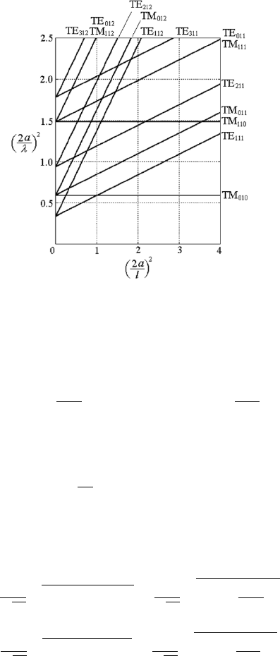
Figure 5.30: Mode-distribution diagram of a circular cylindrical cavity.
respectively. Their solutions are
T
TM
nm
=
x
nm
a
, T
TE
nm
=
y
nm
a
. (5.219)
In order to satisfy the boundary conditions of the short-circuit surfaces at
the two ends, the longitudinal phase coefficient β must be
β
p
=
pπ
l
, p is an integer, (5.220)
where l denotes the length of the cavity.
The natural angular frequencies of TM and TE modes in circular cylin-
drical cavities are then given by
ω
TM
nmp
=
1
√
µ²
q
β
2
p
+ (T
TM
nm
)
2
=
1
√
µ²
r
β
2
p
+
³
x
nm
a
´
2
, (5.221)
ω
TE
nmp
=
1
√
µ²
q
β
2
p
+ (T
TE
nm
)
2
=
1
√
µ²
r
β
2
p
+
³
y
nm
a
´
2
. (5.222)
The mode-distribution diagram of circular cylindrical cavity is given in
Fig. 5.30. We can see that the dominant mode is TE
111
when the length is
larger than the diameter, i.e., a slim cavity; and the dominant mode is TM
010
when the length is smaller than the diameter, i.e., a wide cavity.