Zhang K., Li D. Electromagnetic Theory for Microwaves and Optoelectronics
Подождите немного. Документ загружается.

7.7 The Helix 431
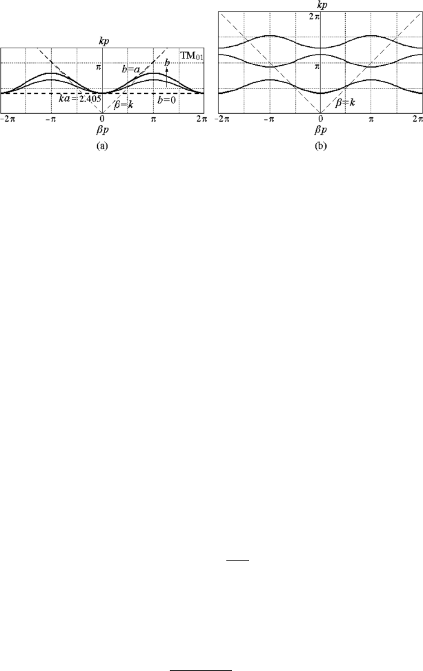
Figure 7.16: The k–β diagrams of the dominant mode (a) and some lower
modes (b) in a disk-loaded waveguide.
The two functions J
0
(x/2) and sinc(x/2) are similar when x is not large, see
Fig 7.15(b).
The k–β diagram of the dominant mode, i.e., the azimuthal invariant TM
modes in a disk-loaded waveguide with center coupling holes as a periodic
system is given in Fig. 7.16(a). The k–β diagram of some lower modes are
shown in Fig. 7.16(b).
7.7 The Helix
The earliest slow-wave structure used in a traveling-wave tube invented by
R.Kompfner is the helix. It is employed in all low- and medium-power
traveling-wave amplifiers and backward-wave oscillators. It is also used in
highly directive broad-band antennas and in high-frequency delay lines.
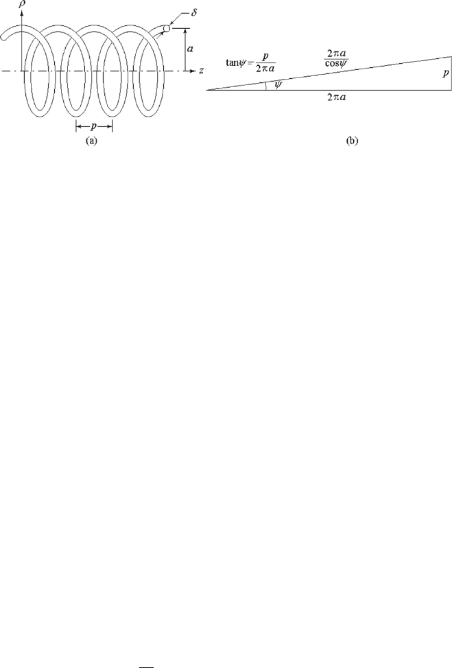
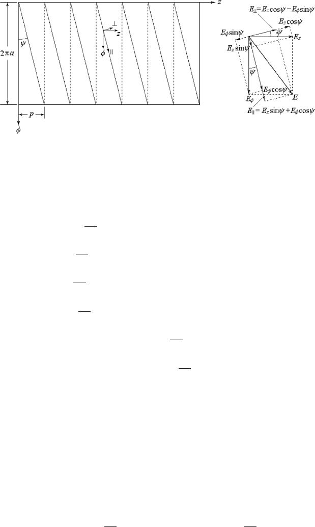
The helix is made of metallic wire as shown in Fig. 7.17 (a). The average
radius of the helix is a, the pitch of the winding, i.e., the period is p, and the
diameter of the wire is δ. The expanded view of a helix is shown in Fig. 7.17
(b). The ratio of the pitch p to the circumference 2πa is the tangent of the
pitch angle ψ,
tan ψ =
p
2πa
. (7.103)
Initially, people proposed that an electromagnetic wave propagates along the
helical wire with the speed of light c, and that the velocity of the wave in
the direction of z is equal to the ratio of the pitch of the winding p to the
circumference 2πa/ cos ψ times the speed of light:
v
z
=
p
2πa/ cos ψ
c = sin ψ. (7.104)
This is the simplest model of a helix and is known as the helical wave model.
According to this model, v
z
is independent of the frequency. That is to say
432 7. Periodic Structures and the Coupling of Modes
Figure 7.17: The helix (a) and its expanded view (b).
that the system is non-dispersive. This conclusion is correct in the high-
frequency regime but in the low-frequency regime, a practical helix does
become a dispersive system.
The boundary conditions of helix are rather complicated and difficult to
deal with for finding the field solution. Hence a number of physical models
have been put forward by different authors. Among them the simplest and
most successful models are the sheath helix and tape helix.
7.7.1 The Sheath Helix
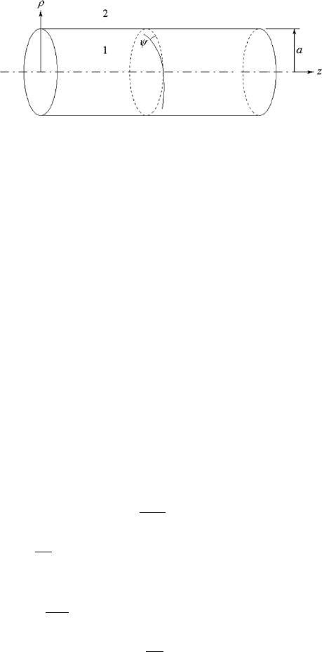
A physical abstraction, known as the sheath helix, given by J. R. Pierce [79]
yields solutions to Maxwell’s equations which show many of the properties of
an actual helix. The sheath helix is a cylindrical surface, i.e., a infinitesimally
thin cylinder, conducting only in the helical direction, as shown in Fig 7.18.
The sheath is perfectly conducting in a direction making an angle ψ with the
plane perpendicular to the axis, but it is nonconducting in the direction nor-
mal to the direction of conduction. A physical approximation to this model
could be reasonably made by winding a flat tape of width p consisting of a
large number of fine wires all insulated with each other on a cylindrical form
of radius a, with all the windings being wound side by side. This structure
would be a perfect sheath helix if the diameter of the wires approaches zero
and the number of wires in the tape approaches infinity. The sheath model
is found to be a good approximation to the actual helix at frequencies and
for modes for which there are many turns per guided wavelength,
λ
z
2
À p, i.e., βp ¿ π.
This is exactly the condition required by the approach in which the validity
of the uniform system is assumed.
7.7 The Helix 433
Figure 7.18: The sheath helix.
(1) General Solutions
Because of the skew and anisotropic boundary conditions it is necessary to
have both TE and TM fields present in a certain mode, so neither U nor V
can be zero. Since we expect slow waves rather than fast waves, the field
components are written in the slow-wave form in both region 1 and region
2. For a slow wave in circular cylindrical coordinates, the functions in ρ
must be modified Bessel functions. The functions in φ are e
jnφ
, where n = 0
for axially symmetric modes or meridional waves, n is a positive integer for
counterclockwise skew-wave modes and n is a negative integer for clockwise
skew-wave modes.
Region 1 (ρ ≤ a): The axis, ρ = 0, is included in the region, hence the
coefficients of functions K
n
must be zero in order to avoid singularity, then
U
1
= A
n
I
n
(τρ)e
jnφ
e
−jβz
, V
1
= B
n
I
n
(τρ)e
jnφ
e
−jβz
,
and the field components are
E
z1
= −τ
2
A
n
I
n
(τρ)e
jnφ
e
−jβz
, (7.105)
E
ρ1
=
·
−jβτA
n
I
0
n
(τρ) +
ωµn
ρ
B
n
I
n
(τρ)
¸
e
jnφ
e
−jβz
, (7.106)
E
φ1
=
·
nβ
ρ
A
n
I
n
(τρ) + jωµτ B
n
I
0
n
(τρ)
¸
e
jnφ
e
−jβz
, (7.107)
H
z1
= −τ
2
B
n
I
n
(τρ)e
jnφ
e
−jβz
, (7.108)
H
ρ1
=
·
−
ω²n
ρ
A
n
I
n
(τρ) − jβτB
n
I
0
n
(τρ)
¸
e
jnφ
e
−jβz
, (7.109)
H
φ1
=
·
−jω²τA
n
I
0
n
(τρ) +
nβ
ρ
B
n
I
n
(τρ)
¸
e
jnφ
e
−jβz
. (7.110)
Region 2 (ρ ≥ a): Infinity, ρ → ∞, is included in the region, hence the
coefficients of functions I
n
must be zero in order to avoid singularity, then
U
2
= C
n
K
n
(τρ)e
jnφ
e
−jβz
, V
2
= D
n
K
n
(τρ)e
jnφ
e
−jβz
,
434 7. Periodic Structures and the Coupling of Modes
and
E
z2
= −τ
2
C
n
K
n
(τρ)e
jnφ
e
−jβz
, (7.111)
E
ρ2
=
·
−jβτC
n
K
0
n
(τρ) +
ωµn
ρ
D
n
K
n
(τρ)
¸
e
jnφ
e
−jβz
, (7.112)
E
φ2
=
·
nβ
ρ
C
n
K
n
(τρ) + jωµτ D
n
K
0
n
(τρ)
¸
e
jnφ
e
−jβz
, (7.113)
H
z2
= −τ
2
D
n
K
n
(τρ)e
jnφ
e
−jβz
, (7.114)
H
ρ2
=
·
−
ω²n
ρ
C
n
K
n
(τρ) − jβτD
n
K
0
n
(τρ)
¸
e
jnφ
e
−jβz
, (7.115)
H
φ2
=
·
−jω²τC
n
K
0
n
(τρ) +
nβ
ρ
D
n
K
n
(τρ)
¸
e
jnφ
e
−jβz
. (7.116)
The relation among β, τ, and k is given by
β
2
− τ
2
= k
2
= ω
2
µ². (7.117)
The boundary conditions at ρ = a are as follows. The electric field com-
ponents in the direction of conduction must be zero
E
1k
(a) = 0, E
2k
(a) = 0, (7.118)
and those normal to the direction of conduction must be continuous
E
1⊥
(a) = E
2⊥
(a). (7.119)
The magnetic field components in the direction of conduction must be con-
tinuous, because there is no surface current normal to the magnetic fields,
H
1k
(a) = H
2k
(a). (7.120)
The subscript k denotes the components parallel to the direction of the helical
wire and ⊥ denotes the components normal to the direction of the helical
wire. The relations among the k, ⊥ and the z, φ components are shown in
Fig. 7.19.
E
k
= E
z
sin ψ + E
φ
cos ψ, E
⊥
= E
z
cos ψ − E
φ
sin ψ,
H
k
= H
z
sin ψ + H
φ
cos ψ, H
⊥
= H
z
cos ψ − H
φ
sin ψ.
Then the boundary conditions (7.118) may be written in terms of the field
components of (7.105)–(7.116) as follows:
E
z1
sin ψ + E
φ1
cos ψ = 0, (7.121)
E
z2
sin ψ + E
φ2
cos ψ = 0, (7.122)
E
z1
cos ψ − E
φ1
sin ψ = E
z2
cos ψ − E
φ2
sin ψ, (7.123)
H
z1
sin ψ + H
φ1
cos ψ = H
z2
sin ψ + H
φ2
cos ψ. (7.124)
7.7 The Helix 435
Figure 7.19: The expanded view of a sheath helix and the helical coordinates.
Substituting (7.105) through (7.116) into them, yields
µ
−τ
2
sin ψ +
nβ
a
cos ψ
I
n
(τa)A
n
+ jωµτ I
0
n
(τa) cos ψB
n
= 0, (7.125)
µ
−τ
2
sin ψ +
nβ
a
cos ψ
K
n
(τa)C
n
+ jωµτ K
0
n
(τa) cos ψD
n
= 0, (7.126)
µ
−τ
2
cos ψ −
nβ
a
sin ψ
I
n
(τa)A
n
− jωµτ I
0
n
(τa) sin ψB
n
+
µ
τ
2
cos ψ +
nβ
a
sin ψ
K
n
(τa)C
n
+ jωµτ K
0
n
(τa) sin ψD
n
= 0, (7.127)
−jω²τI
0
n
(τa) cos ψA
n
+
µ
−τ
2
sin ψ +
nβ
a
cos ψ
I
n
(τa)B
n
+jω²τK
0
n
(τa) cos ψC
n
+
µ
τ
2
sin ψ −
nβ
a
cos ψ
K
n
(τa)D
n
= 0. (7.128)
This is a set of homogeneous linear equations with variables A
n
, B
n
, C
n
, and
D
n
. The homogeneous equations are satisfied simultaneously by nontrivial
solutions only when the determinant of the coefficients vanishes.
¯
¯
¯
¯
¯
¯
¯
¯
−Ψ
1
I
n
(τa) Φ
1
I
0
n
(τa) 0 0
0 0 −Ψ
1
K
n
(τa) Φ
1
K
0
n
(τa)
−Ψ
2
I
n
(τa) −Φ
2
I
0
n
(τa) Ψ
2
K
n
(τa) Φ
2
K
0
n
(τa)
−Φ
3
I
0
n
(τa) −Ψ
1
I
n
(τa) Φ
3
K
0
n
(τa) Ψ
1
K
n
(τa),
¯
¯
¯
¯
¯
¯
¯
¯
= 0,
where
Ψ
1
= τ
2
sin ψ −
nβ
a
cos ψ, Ψ
2
= τ
2
sin ψ +
nβ
a
cos ψ.
436 7. Periodic Structures and the Coupling of Modes
Φ
1
= jωµτ cos ψ, Φ
2
= jωµτ sin ψ, Φ
3
= jω²τ cos ψ.
After going through a lot of algebra, we obtain the eigenvalue equation:
I
n
(τa)K
n
(τa)
I
0
n
(τa)K
0
n
(τa)
= −
k
2
a
2
τ
2
a
2
cot
2
ψ
(τ
2
a
2
− nβa cot ψ)
2
. (7.129)
Following this eigenvalue equation and equation (7.117), the propagation
characteristics of the sheath helix for different modes are given.
The relations of the coefficients in the field-component expressions are
also obtained from (7.125)–(7.128) as follows:
B
n
=
τ
2
a
2
− nβa cot ψ
jωµτa
2
cot ψ
I
n
(τa)
I
0
n
(τa)
A
n
, (7.130)
C
n
=
I
n
(τa)
K
n
(τa)
A
n
, (7.131)
D
n
=
I
0
n
(τa)
K
0
n
(τa)
B
n
=
τ
2
a
2
− nβa cot ψ
jωµτa
2
cot ψ
I
n
(τa)
K
0
n
(τa)
A
n
. (7.132)
Substituting these into (7.105)–(7.116), we have the final expressions of the
field components inside and outside the helical sheath. Only one coefficient
A
n
remains in the expressions, which is determined by the amplitude of the
wave of the nth mode propagating in the guided-wave system.
(2) The Dominant Mode
The dominant mode in the helix is the azimuthal uniform mode, i.e., the
mode for which n = 0. The phase velocity of the n = 0 mode is nearly equal
to the group velocity and is nearly constant for relatively high frequencies,
which is approximately equal to the value we estimated earlier by means of
the helical wave mo del (7.104). This mode is the commonly used as slow-wave
structure in traveling-wave amplifiers and delay lines.
For n = 0, the co efficients in the field comp onent expressions (7.130)–
(7.132) become
B =
τ
jωµ cot ψ
I
0
(τa)
I
1
(τa)
A, (7.133)
C =
I
0
(τa)
K
0
(τa)
A, (7.134)
D = −
τ
jωµ cot ψ
I
0
(τa)
K
1
(τa)
A, (7.135)
and the field components inside and outside the sheath become
E
z1
= −τ
2
A
0
I
0
(τρ)e
−jβz
, (7.136)
E
ρ1
= −jβτ A
0
I
1
(τρ)e
−jβz
, (7.137)
7.7 The Helix 437
E
φ1
=
τ
2
cot ψ
I
0
(τa)
I
1
(τa)
A
0
I
1
(τρ)e
−jβz
, (7.138)
H
z1
= −
τ
3
jωµ cot ψ
I
0
(τa)
I
1
(τa)
A
0
I
0
(τρ)e
−jβz
, (7.139)
H
ρ1
= −
βτ
2
ωµ cot ψ
I
0
(τa)
I
1
(τa)
A
0
I
1
(τρ)e
−jβz
, (7.140)
H
φ1
= −jω²τA
0
I
1
(τρ)e
−jβz
. (7.141)
E
z2
= −τ
2
I
0
(τa)
K
0
(τa)
A
0
K
0
(τρ)e
−jβz
, (7.142)
E
ρ2
= jβτ
I
0
(τa)
K
0
(τa)
A
0
K
1
(τρ)e
−jβz
, (7.143)
E
φ2
=
τ
2
cot ψ
I
0
(τa)
K
1
(τa)
A
0
K
1
(τρ)e
−jβz
, (7.144)
H
z2
=
τ
3
jωµ cot ψ
I
0
(τa)
K
1
(τa)
A
0
K
0
(τρ)e
−jβz
, (7.145)
H
ρ2
= −
βτ
2
ωµ cot ψ
I
0
(τa)
K
1
(τa)
A
0
K
1
(τρ)e
−jβz
, (7.146)
H
φ2
= jω²τ
I
0
(τa)
K
0
(τa)
A
0
K
1
(τρ)e
−jβz
. (7.147)
For n = 0, The eigenvalue equation (7.129) becomes
I
0
(τa)K
0
(τa)
I
1
(τa)K
1
(τa)
=
µ
k
τ
cot ψ
2
, or (τa)
2
I
0
(τa)K
0
(τa)
I
1
(τa)K
1
(τa)
= (ka cot ψ)
2
. (7.148)
These equations are solved by solving for (k/τ ) cot ψ and ka cot ψ in terms
of the value of τ a. The solutions are plotted in Fig. 7.20 and are known as
the normalized disp ersion curves of the dominant mode on sheath helix and
are independent of the dimensions of the helix.
The actual dispersion curves may be plotted when the pitch angle ψ or
the average diameter of the helix a and the pitch p is given. The dep endencies
of the slow-wave ratio v
p
/c = ka/βa and normalized frequency ωa/c = ka
are plotted for several pitch angles in Fig. 7.21.
When the frequency is sufficiently high, i.e., ka cot ψ is sufficiently large,
we see from equation (7.148), Fig. 7.20 and Fig. 7.21 that (k /τ ) cot ψ → 1
and the longitudinal phase constant β and the slow-wave ratio become
β ≈ k
q
1 + cot
2
ψ,
v
p
c
=
k
β
≈ sin ψ. (7.149)
This is just the value we estimated earlier by means of the helical wave model
(7.104).
When the frequency is low, i.e., ka cot ψ is small, the slow-wave ratio is
larger than sin ψ. Moreover, when ω → 0 or ψ → π/2, i.e., ka cot ψ → 0, we
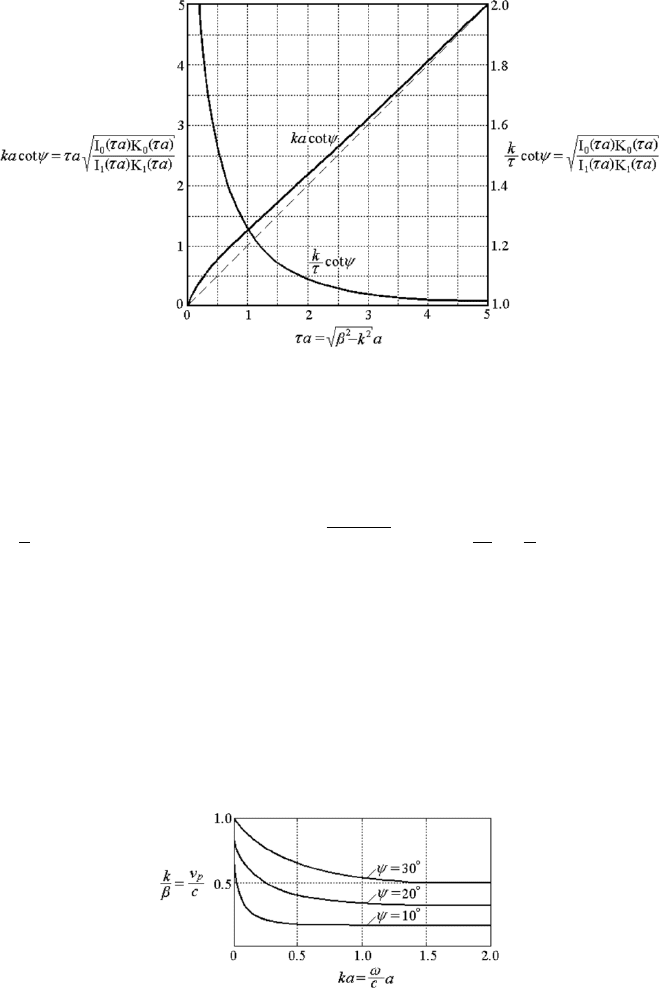
438 7. Periodic Structures and the Coupling of Modes
Figure 7.20: Normalized dispersion curves of the dominant mode on a sheath
helix.
see from equation (7.148), Fig. 7.20 and Fig. 7.21 that
k
τ
cot ψ → ∞, τ ¿ k, β =
p
k
2
+ τ
2
≈ k,
v
p
c
=
k
β
≈ 1. (7.150)
The longitudinal phase velocity tends to approach the speed of light at very
low frequencies.
A plot of the field configuration within a longitudinal section of the sheath
helix is given in Fig. 7.22. When the frequency is sufficiently high, the elec-
tric and magnetic flux lines are inclined approximately by an angle ψ and
are approximately confined on the plane normal to the helical direction of
conduction. The Poynting vector is then in the helical direction. This is
Figure 7.21: Dispersion curves of the dominant mode on a sheath helix.
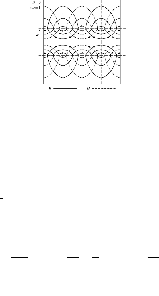
7.7 The Helix 439
Figure 7.22: Field configuration of the dominant mode on a sheath helix.
nothing but a nonuniform plane wave or TEM wave propagating in the heli-
cal direction. When the frequency is low, the angle of inclination of the flux
lines is no longer ψ, the direction of the Poynting vector is oriented towards
the longitudinal axis z and the longitudinal phase velocity tends to c.
All the fields inside and outside the helix are traveling waves in z and
decaying fields in ρ. Such waves are surface waves. The field strength at the
axis is smaller than that at the sheath surface. See Fig. 7.23.
The interaction impedance of the dominant mode on a sheath helix is
obtained by substituting the field components (7.136)–(7.147) into (7.1), in
which
P =
1
2
<
·
Z
a
0
¡
E
ρ1
H
∗
φ1
−E
φ1
H
∗
ρ1
¢
2πρ dρ+
Z
∞
a
¡
E
ρ2
H
∗
φ2
−E
φ2
H
∗
ρ2
¢
2πρ dρ
¸
.
The interaction impedance on the axis is then given by
K(0) =
E
2
zm
(0)
2β
2
P
=
β
k
µ
τ
β
4
F (τa), (7.151)
where
F (τa) =
(
π(τa)
2
η
"
¡
I
2
1
−I
0
I
2
¢
µ
1+
I
0
K
1
I
1
K
0
+
µ
I
0
K
0
2
¡
K
0
K
2
−K
2
1
¢
µ
1+
I
1
K
0
I
0
K
1
#)
−1
.
Applying the recurrence formulas (C.14), (C.15) and Wronskian (C.28), we
reduces F (τ a) to
F (τa) =
½
πτa
η
I
0
K
0
·µ
I
1
I
0
−
I
0
I
1
+
µ
K
0
K
1
−
K
1
K
0
+
4
τa
¸¾
−1
.

440 7. Periodic Structures and the Coupling of Modes
Figure 7.23: The ρ dependence of the field components of the dominant mode
on a sheath helix.
All the arguments of the modified Bessel functions are τa.
The off-axis interaction impedance at ρ = b is
K(b) = K(0)I
2
0
(τb), (7.152)
which is higher than that on the axis.
The average interaction impedance in an electron beam of radius b is given
by
K =
1
πb
2
Z
b
0
Z
2
0
πK(0)I
2
0
(τρ)ρ dφ dρ = K(0)
£
I
2
0
(τb) − I
2
1
(τb)
¤
. (7.153)
See Fig. 7.24.
The interaction impedance of an actual helix is lower than that predicated
for the ideal sheath helix because of the influences of the space harmonics
and the dielectric holder of the wire helix.
(3) The Higher Modes
Rewrite the transcendental eigenvalue equation for sheath helix (7.129),
I
n
(τa)K
n
(τa)
I
0
n
(τa)K
0
n
(τa)
= −
k
2
a
2
τ
2
a
2
cot
2
ψ
(τ
2
a
2
− nβa cot ψ)
2
.
The solutions to the eigenvalue equation for general cases are shown in
Fig. 7.25 as the solid lines. The shaded region in the figure is a forbid-
den region because the helix is an unbounded structure. The dominant mode