Yao N. Focused Ion Beam Systems: Basics and Applications
Подождите немного. Документ загружается.

Because of its light optical nature, the lateral resolution of a confocal micro-
scope is limited to about 0.2 mm, where its vertical resolution is worse at about
0.5 mm. Sample sizes are on the order of 1 mm. In the same order of magnitude
of resolution performance, X-ray tomography is a well-known technique that
works with similar-sized samples, and is nondestructive. It is based on
recording the attenuation of X-rays as they travel through the sample material,
to produce a two-dimensional image. A series of 2D images is recorded along
the length of an object, to form a complete 3D representation. In order to
obtain the best spatial resolution (1 m m), a synchrotron X-ray source is used.
Three to four orders of magnitude lower in resolution as well as sample size,
TEM tomography is an extremely powerful technique for analyzing small
volumes of material (typically a few mm
2
in surface area and not more than a
few hundred nanometers thick). Using dedicated sample holders, a series of
images is recorded at various angles of tilt between electron beam and specimen
(typically 70 to þ70
). The resulting dataset is deconvoluted offline into a 3D
model that can be visualized. Finally, atom probe or field-ion microscopy
(FIM) techniques enable 3D characterization with true atomic resolution.
Using a very thin and sharp needle-like specimen, sample ions are field emitted
by a strong electrical field applied to the specimen tip. Three-dimensional
elemental information is obtained from combined time-of-flight (TOF) mass
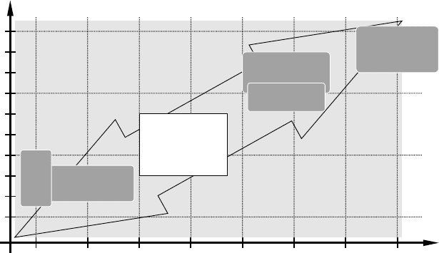
Sample length scale (m)
T
yp
ical s
p
atial resolution (m)
10
–9
10
–8
10
–7
10
–6
10
–5
10
–4
10
–3
µm mmnm
10
–10
Å
10
–9
10
–6
10
–3
1
MRI
X–ray
tomography
Confocal
microscopy
TEM
tomography
Atom
probe
FIB/SEM
Tomography
Figure 5.1 Graph showing the typical spatial resolution and sample size
of some contemporary techniques for three-dimensional characterization.
The obtained resolution scales roughly linea rly with the sample size. FIB/
SEM tomography clearly fills an obvious gap in the range of available
techniques.
Focused ion beam systems128
spectrometry and a position-sensitive detector. However, the technique is
typically limited to conductive samples with small taper angle and a very small
tip radius (< 50 nm), which requires extensive preparation. Interestingly, FIB
has proven to be an excellent preparation method for this type of sample [5].
However, the analyzed volume is not more than a cubic micrometer.
From Figure 5.1 and the description above, it is clear that these techniques
leave an important gap in the accessible dimensional space, corresponding to
sample length scales of hundreds of nanometers to hundreds of micrometers.
That gap is almost perfectly addressed by FIB/SEM tomography using serial
sectioning: SEM imaging resolution ranges down to roughly 1 nm. A prac-
tical lower size limit for the FIB ‘‘slices’’ is found to be of the order of
magnitude of 10 nm. Analyzed sample sizes range from just sub-micrometer
to about 100 mm in length scale. This range of resolution/sample size is found
to fit almost perfectly in the existing gap, as can be seen from Figure 5.1.
5.2.1 From a single cross section to serial sectioning –
Auto (Slice and View)
It is well known that FIB is an excellent tool for specimen preparation,
amongst others, for subsequent SEM or FIB observation. Specifically, the
cross-sectioning capabilities of FIB provide a precise, site-specific, and efficient
means for looking below the surface, i.e., ‘‘into’’ the bulk of a sample. Even
more efficient to this end, is the combination of an FIB and SEM column on
one platform (i.e., a DualBeam instrument). This allows the operator to switch
from FIB sectioning to SEM observation, and back, in a matter of seconds or,
even monitor a machining process directly via simultaneous patterning and
imaging (SPI). SPI mode will be described in detail below.
The resulting image of such an FIB prepared cross section yields two-
dimensional information about the cross-sectioned plane only. In a Dual-
Beam, however, it is possible to extend this technique to multiple serial cross
sections in a very straightforward way: why not, after acquiring an image of the
original cross section, ‘‘peel’’ off another thin layer of the polished surface by
FIB milling, and acquire a second image? The second cross-sectional image
yields similar information as the first one, only this time from a slightly shifted
position in the volume of the sample. This alternating sequence of cutting
and imaging steps can be repeated over and over, until a sufficiently large
volume of the sample has been cross-sectioned and imaged. This process is
illustrated schematically in Figure 5.2. The result is a series of ‘‘images’’ of a
volume, instead of one 2D planar image. The dataset thus inherently contains
true three-dimensional information about the sample.
Characterization methods using FIB/SEM DualBeam instrumentation 129
The ‘‘images’’ from the dataset can be (but are not limited to) SEM
induced images (secondary electron or backscattered electron images), FIB
induced images (secondary electron or secondary ion images), and/or com-
plete EDS and even EBSD maps. Depending on the type of data acquired on
a specific class of microscope, manipulation of the sample position may be
needed between milling and imaging. The different combinations discussed
above are summarized in Table 5.1.
Besides indicating for the need of sample position manipulation, Table 5.1
also gives a typical cycle time. This time encompasses the four steps in a cycle:
the actual time spent milling (FIB); the sample repositioning for data
acquisition, when applicable; the actual data acquisition time (can vary
greatly between just an image, or a complete EBSD map); and the sample
repositioning for milling, when applicable. The cycle time given is ‘‘typical,’’
i.e., for a cross section of reasonable size (e.g. 10 mm wide and 3 mm deep)
and normal milling and imaging parameters. Of course, timing can vary
greatly with the cross section size, milling current, imaging speed, and a
number of other parameters.
Practical total acquisition times range from a couple of hours to tens of
hours, translating into a total number of tens to thousands of slices. Slice
thickness and magnification are mainly dictated by the size of the features
that are to be analyzed; ideally the slice thickness and lateral image resolution
FIB
SEM
FIB
SEM
(a) (b)
Figure 5.2 A schematic diagram of (a) the concept of a cross section, milled
and imaged in a DualBeam and (b) the concept of multiple, serial cross
sections where the dashed boxes represent thin layers of material that are
polished off sequentially after SEM imaging.
Focused ion beam systems130

are at least ten times smaller than the smallest features. In practice, lateral
resolution as well as slice thickness of approximately 10 nm can be obtained
in a process that runs for multiple hours. Slice thickness is limited by the
precision of ion beam positioning, as well as system drift throughout the
entire process. Using thicker slices, a realistic size limit for the analyzed
volume is around a length scale of 100 mm (resulting in a total maximum
analyzed volume of 1 000 000 mm
3
).
Although in principle there is no real limit to the magnification range that
can be used, to the size of the volume that can be analyzed, or to the slice
density that can be sliced (inversely proportional to the slice thickness),
practical limitations are imposed directly or indirectly by time constraints.
Assuming a typical and reasonably sized dataset consists of 100–500 slices,
the total time that is needed to acquire such a large amount of data is quite
long. Therefore, one quickly faces total times on the machine from a couple
of hours to tens of hours. This reflection automatically leads to the benefit
and even necessity to automate such long tasks. Besides taking away a large
burden from the operator, automation will also improve overall speed and
reproducibility of the results. In the example below, the utilization of FEI’s
Auto (Slice and View) automation software to acquire hundreds of serial
slices overnight using a Nova NanoLab 600 DualBeam is demonstrated. The
automation software allows for compensation of the slightly increasing focal
length, as well as for the apparent upward shift of the cross-sectional surface
within the field of view, during the slicing process. Both effects are caused by
the combination of subsequent material removal and the SEM observation of
the cross section under a tilt angle.
Table 5.1. Different types of information can be obtained from serial sectioning.
Depending on the instrument class, sample position manipulation will be needed or not.
This table summarizes the possibilities and limitations (n/a in the FIB section means this
combination is not applicable since it requires a primary electron beam).
Instrument type
Type of ‘‘image’’
(data) acquired
Sample position
manipulation? Typical cycle time
DualBeam SEM (SE, BSE) No 1–5 minutes
FIB (SE, SI) Yes 2–10 minutes
EDS No 2–15 minutes
EBSD Yes 5–30 minutes
FIB only SEM (SE, BSE) n/a n/a
FIB (SE, SI) Yes 2–10 minutes
EDS Yes Currently not known
EBSD n/a n/a
Characterization methods using FIB/SEM DualBeam instrumentation 131
Before describing a practical example, it should be mentioned that FIB
cross-sectioning is inherently a destructive process, and therefore also serial
sectioning is a destructive process. In order for the electron beam (SEM
imaging) to access the deeper-lying volume, the material ‘‘in between’’ has to
be milled away. Although this material removal is irreversible, the sample
modification is only very local, leaving the remainder of the bulk material
intact.
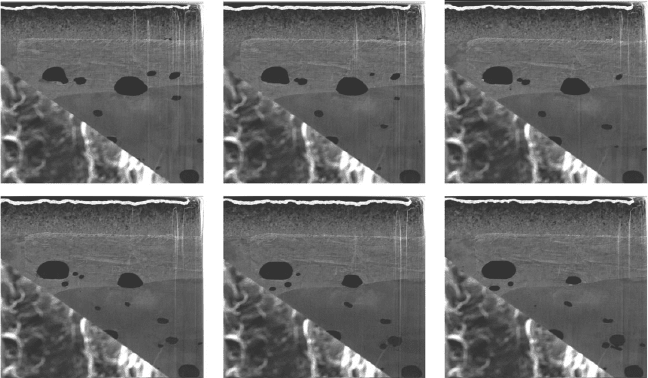
An Auto (Slice and View) dataset was acquired overnight on a sample
consisting of a copper substrate with a copper coating containing iron oxide
inclusions, a nickel coating, and a very thin gold coating. The raw dataset
consists of 283 slices with dimensions 16 · 13.8 mm
2
. Each slice is recorded as
a 1024 · 884 pixel SEM image. Figure 5.3 shows a selection of six slices from
this dataset. The total acquisition time is approximately 14 hours, roughly
half of which is spent acquiring images and the other half milling slices.
The size of the complete 3D dataset will have implications when storing it
on a hard disk, transporting it over a computer network, and manipulating
it offline for further processing and visualization: in the example, the total
size of this moderate dataset is about 250 MB.
5.2.2 3D reconstruction
Three-dimensional analysis using FIB tomography is essentially a two-step
process. After acquisition of the raw data as described above, this dataset is
Figure 5.3 A selection of six SEM images after FIB slicing. The complete
dataset consisted of 283 images.
Focused ion beam systems132
taken offline for further processing and 3D visualization. This second step is
described in this paragraph, by means of the practical example introduced
above. We first describe the different steps to be taken, then an example using
a specific software package is given. It should be noted that multiple software
packages performing similar processing and visualization steps are com-
mercially available.
The entire workflow is illustrated in the schematic diagram of Figure 5.4.
After initial cross-section machining and raw data acquisition in the FIB or
DualBeam, one ends up with a stack of images. The content of this stack are
equidistant cross sections through the analyzed volume.
Offline processing starts with initial data cropping. Though not strictly
necessary, this optional step often enables irrelevant data to be discarded (e.g.,
parts of the image that do not contain cross-sectional information but rather
the outer parts of the sample surface), thereby effectively reducing the size of
the entire dataset, which in turn results in more efficient manipulation and
processing. Then, the image stack may be preprocessed to improve image
quality. The preprocessing usually involves application of image filters to the
entire data set to remove noise and artefacts, smooth or sharpen the images,
or improve contrast and brightness. Inter-slice alignment is usually the next
step performed. This can be done by hand (obviously very labour intensive
and time consuming on large stacks) or by using an automated algorithm,
and is often useful on high-magnification datasets to reduce the effects of
drift or small system instabilities. Inter-slice alignment inevitably results in
some data points being present on the periphery of the images, where data
are not present throughout the entire stack. This is due to shifting of the
images relative to one another. Since these data points are no longer useful,
they are cropped away in a second cropping step.
In principle, the dataset is now ready for visualization, although depending
on the rendering method (see below), it may be needed to highlight certain
features in the images, throughout the entire stack, in a segmentation
In-situ (FIB/DualBeam) Offline
• FIB cross-section
machining
• Raw data acquisition
loop using “Auto (Slice
and View)” or similar
• Data cropping
• Preprocessing (filtering)
• (automated) inter-slice
fine alignment
• Data cropping
• Segmentation (feature
selection)
• Visualization
Figure 5.4 A schematic diagra m of the FIB tomography workflow.
Characterization methods using FIB/SEM DualBeam instrumentation 133
operation. This allows, for instance, displaying only some inclusions in a
bulk, thereby highlighting only the interesting or relevant parts of the data.
Visualization itself can be done in many different ways, depending on the
possibilities of the actual software used, the information that one is after, and
the quality of the original dataset. The most basic and often very useful way
is to show (orthogonal) sections through the volume, thereby enabling virtual
cross-sectioning through an arbitrary plane. Alternatively, the dataset can be
reconstructed into a 3D volumetric dataset. This is achieved using volume or
surface rendering techniques. For volume rendering, the dataset is subdivided
into volumetric building blocks called voxels. A voxel is the 3D counterpart
of a 2D pixel, and in the case of a stack of SEM images, each voxel carries a
gray value based on the original cross-sectional images. For the most pow-
erful and best-balanced visualization possibilities, the voxels should ideally be
cubes. In practice, the slice thickness should not be more than ten times larger
than the lateral resolution in the individual slice images. The 3D voxel sets
are displayed on the computer screen by projecting them onto a planar
surface, whereby the gray value can, for example be translated into a
transparency value. Volumes rendered in this manner often seem to have the
appearance of a translucent suspension of particles in 3D space. In surface
rendering, the volumetric data must somehow be translated into a set of
surfaces, using segmentation techniques. Again this can be done by hand, or
by automated algorithms such as iso-surfacing. The resulting (triangulated)
surfaces are then rendered for display using conventional geometric render-
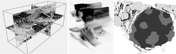
ing techniques. Figure 5.5 shows examples on different samples of each of the
three visualization techniques.
(a) (b) (c)
Figure 5.5 Examples of FIB tomography based 3D characterization using
different visualization techniques. (a) Orthogonal sections through a steel
sample; (b) volume rendering based on voxel transparency of a semicon-
ductor defect; (c) surface rendering after segmentation of a biological cell
sample. The length scale of each of these examples is a few micrometers.
Amira software was used for the visualization.
Focused ion beam systems134
In practice, we believe the calculation of sections through the volume is the
easiest, fastest and simplest way to obtain three-dimensional information. It
enables not only true insight into the 3D structure of the sample, but also
makes measuring in any direction in space straightforward. Volume ren-
dering requires a lot more user interaction, in order to obtain useful results;
however, the final result can be quite rewarding. A disadvantage is the dif-
ficulty of working with large datasets, since this technique is computationally
very intensive. Surface rendering is probably least used, since it requires a
good understanding of the segmentation process, is the most user-intensive,
and needs a powerful computer to be efficient.
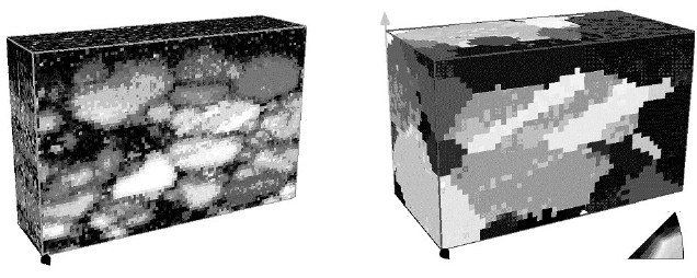
In the case of EDS or EBSD data collection over multiple slices, not only is
the visualization important, but so is the data-mining, i.e., the numerical and
statistical analysis of the results. Figure 5.6 shows a visualization of a dataset
that was acquired using FEI’s ‘‘EBS3’’ package [5,6]. The images are based
on a set of EBSD maps from a thin-film Ni sample with a grain size of about
1 mm. For the entire analyzed volume, or more specifically for each of the
identified grains, statistical data such as three-dimensional grain size
(volume) and orientation, surface area, and the mean grain boundary mis-
orientation, can be automatically extracted.
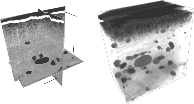
To conclude this part about 3D characterization, we show some practical
results that were obtained on the dataset, originally introduced in Figure 5.3.
Figure 5.7 shows orthogonal sections as well as a volume-rendered repre-
sentation of these data, after alignment and cropping. The visualization
software package used for these examples is Amira.
(a) (b)
[001]
[111]
[101]
Figure 5.6 Examples of SEM/FIB three-dimensional EBSD analysis on a
thin-film Ni sample. (a) Main map consisting of 20 nm wide voxels for a
total analyzed volume of 1940 · 1260 · 500 nm
3
; (b) details of a twinned
grain. Grayscale is indicative of crystal orientation.
Characterization methods using FIB/SEM DualBeam instrumentation 135
5.3 Simultaneous patterning and imaging (SPI mode)
Serial slicing and viewing, as described in the previous section, alternates
between FIB machining and SEM imaging. Essentially, this enables complete
optimization of the parameters used for both techniques independently. This
is not entirely true for simultaneous patterning (milling or deposition) and
imaging. However, simultaneous milling and imaging does have other ben-
efits, not least of all the increased overall operation speed. Therefore, both
techniques should be considered complementary techniques, each exploiting
their own benefits in specific application areas.
Whereas serial slicing and viewing can be performed on a single-beam FIB
instrument, true simultaneous patterning and imaging (SPI) obviously
requires two beams to be on at the same time, and is thus strictly limited to,
at the present time, DualBeam instruments.
5.3.1 Primary beams and detected signals
Obviously, simultaneous patterning and imaging includes, e.g., both a primary
ion beam (patterning) and a primary electron beam (imaging) interacting
with the sample material at the same time. A prerequisite for simultaneous
patterning and imaging is that the ion and electron beams are coincident on
the sample surface, i.e., they should be scanning the identical region of
Axial
Sagittal
Coronal
(a) (b)
Figure 5.7 3D visualization of the dataset introduced in Figure 5.3.
(a) Orthogonal sections clearly reveal the layered struc ture of the sample;
(b) volume-rendering gives an insight into the distribution of the Fe
2
O
3
inclusions in the Cu bulk. Visualization realized using Amira software package.
Focused ion beam systems136
interest on the sample. At their intersection point, the primary ion beam
interacts with the sample to create secondary electrons, sputtered atoms,
secondary ions, and other interaction products. At the same position in the
sample, the primary electron beam generates, amongst others, secondary
electrons, backscattered electrons, and X-rays. For creating an SEM image,
traditionally the secondary electron (SE) or backscattered electron (BSE)
signal is correlated with the scanning of the electron beam. This is not dif-
ferent when using SPI mode.
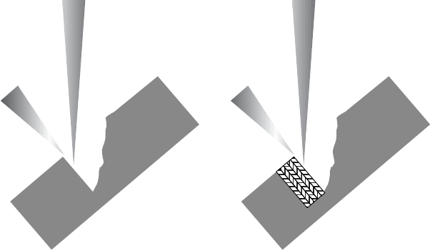
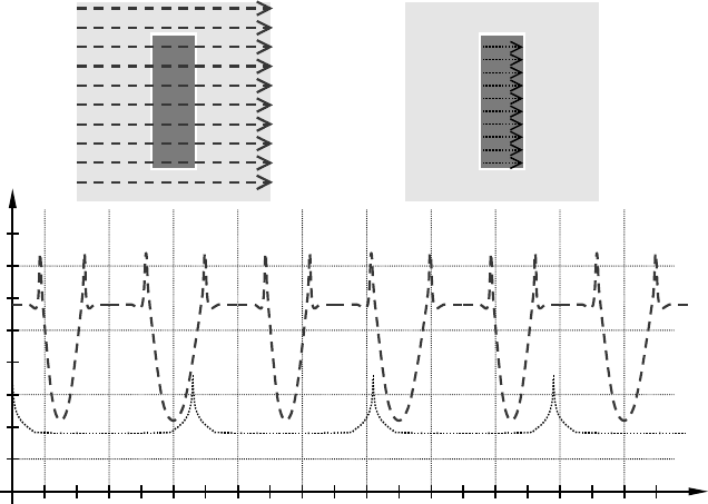
The main difference lies herein, that the FIB also generates an SE signal.
As shown in Figure 5.8, the detector cannot or hardly discriminate between
secondary electrons generated either by the SEM or by the FIB. The figure
shows how the SEM is scanned across a given field of view. In the graph, the
generated SE signal is shown as a gray dashed line: as the electron beam scans
across the partially milled shape, its edges will generate a peak, while the
milled hole itself will appear darker than the original sample surface (topo-
graphy contrast; we assume a uniform material for simplicity). The figure
also shows how the FIB is scanned across the defined pattern, thereby
SE signal (a.u.)
Time (a.u.)
(a)
(b)
(c)
Figure 5.8 Schematic diagram of primary beam scanning and resulting SE
signal. (a) SEM scanning across field of view; (b) FIB scanning across
milling box ; (c) SE signals generated by the SEM alone (gray dashed line)
and the FIB alone (black dotted line). The sum of both is the basis for imag e
formation.
Characterization methods using FIB/SEM DualBeam instrumentation 137